

Members are Working on AP EE
Building a Flashing Crossbuck
During the middle of October TLMRC enjoyed a week long retreat at Windy Pines in Three Lakes WI. This week was filled with trips to enjoy fall colors and explore the railroads of the Upper Peninsula of MI and northern Wisconsin.
We also had 2 workshops at the Fab Lab Three Lakes with Laser cutting and numerous 3 D printing on the uPrint and the MakerBot printers. Paul gave a presentation on the projects of the TLMRC at the Fab Lab Three Lakes.
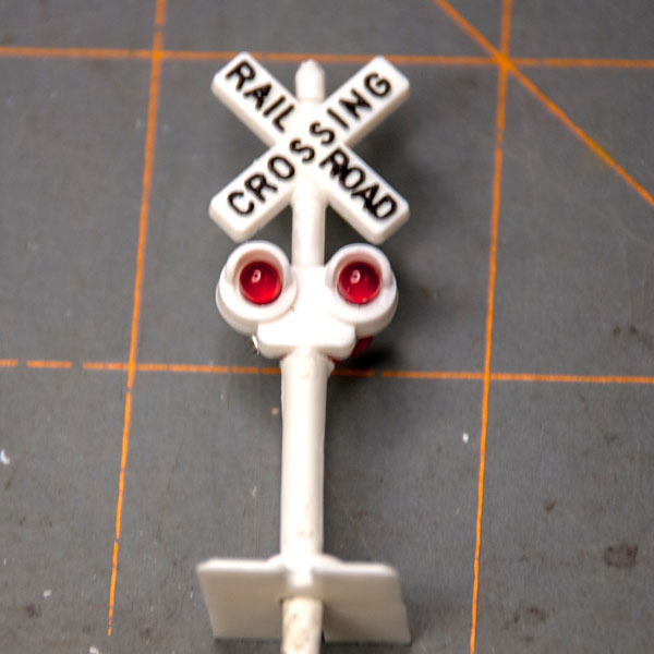
One of our projects in Paul’s Workshop at Windy Pines was to build and wire LED flashing crossing lights. We purchased new packs of 3 mm LEDs and also Miniatronics Dual Emergency Flasher circuits. Unfortunately Paul’s DC power supply was over at Roger’s house and Roger was out of town. Construction on the Windy Pines Layout continued but little was done on the crossing flashers except for drilling out the red plastic fillers from the Crossbucks.
On 11/17/15 we gathered to wire and build the crossbucks in a make and take session. Images here show the project as it was done with the parts from the Choo Choo Store.
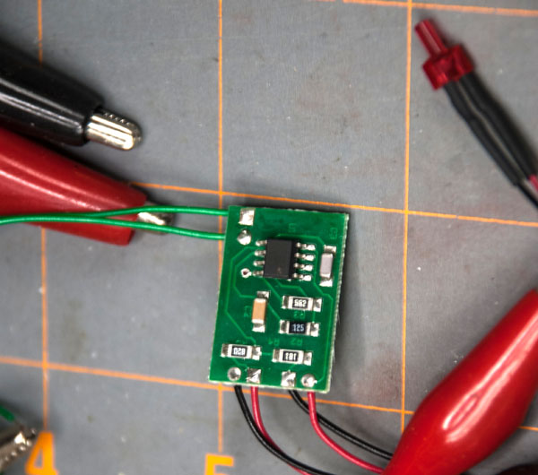
First we tested the Ministronics Dual Emergency Flasher circuit with a DC supply and all worked well. Then it was on to find the polarity of the LED packs we purchased from Dale at the Choo Choo Store. Looking inside the LEDs you can see the difference between the Anode and Cathode and then test the LEDs with the Ministronics Dual Emergency Flasher circuit.
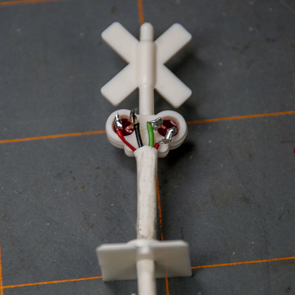
Once this was done the LEDs were wired with #30 wire red, black and green in a 4 wire configuration. This is different from our clinic last year with a 3 wire due to the lack of a common ground on the Ministronics Dual Emergency Flasher circuit. This, in fact, made the assembly easier as the 4 wire did not require the precise spacing of the LED leads when soldering.
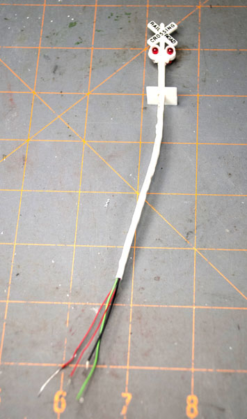
With the 4 wire system each LED was wired and tested after careful soldering using a heat sink to protect the LED from the heat of the solder. Color code of the wires was important in order to allow the correct connection to the Ministronics Dual Emergency Flasher circuit.
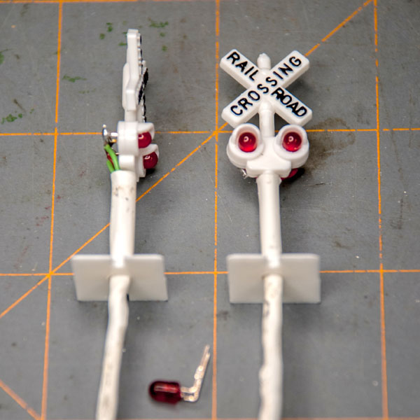
With the wires hooked up and tested the LEDs were put in place white heat shrink tubing was placed over the wires which were located behind the shaft of the crossbuck.
Finished and ready for installation
Updated 11/17/15
Join us in the “Greatest Hobby” as a member of the TLMRC.